This is going to be a little story about electromagnetic interference (EMI). The good thing is: there will be a happy end :)
Having installed all the WS2811 LEDs, I decided to play a quick game to see if everything is still working. It was quite surprising to see the LEDs flicker like a Christmas tree, even though they should have been dark. This happened everytime the flipper coils actuated. Clearly there was some kind of EMI problem, inducing noise on the data line of the LEDs.
A quick scope measurement on the solenoids revealed the issue:

Note that at this time I still had some random PN diode directly across the solenoids terminal.

I saw > 60 V voltage spikes when the coil was switched ON. Note that this pulse happened 20000 times a second, with the PWM frequency.

Then I measured right on the solenoid driver board. At this point there was no recovery diode here at all.

Again I measured 60 V spikes and strong ringing. Clearly this was the reason my LEDs freaked out.

To get rid of those spike, I tried various combination of putting components across the solenoid or the solenoid driver outputs:
- Fast Schottky diode
- 4.7 nF Capacitor
- 4.7 nF Capacitor + 47 Ohm resistor in series (snubber circuit)
Adding the capacitor changed the resonant frequency of the ringing, but not the amplitude. The snubber circuit helped slightly. The Schottky diode had the most positive effect, especially if put on the solenoid driver board.

So what was going on? I think the problem was the parasitic inductance of the cables to the solenoid. The cables themselves also act like an inductor, hence also have a freewheeling current when switched off, and having installed the freewheeling diodes on the solenoid itself, there was no path for this current to go.
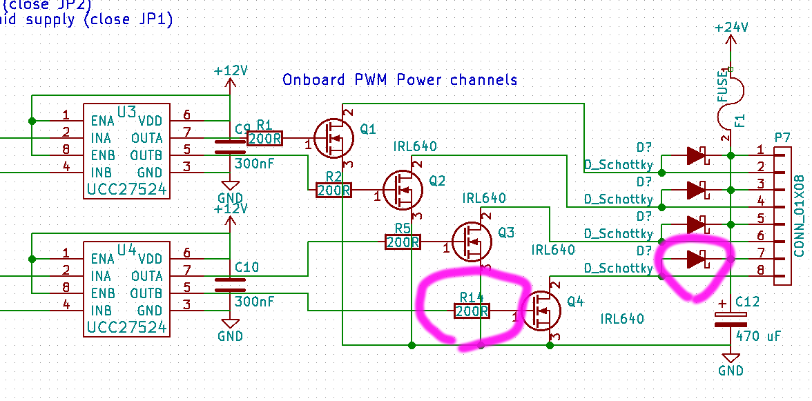
I got rid of the spikes by changing 3 things:
- I installed the diodes right on the solenoid driver board. This way they also provide a path for the freewheeling currents of the cables
- I installed Schottky diodes (1N5822), which do not have a reverse recovery time and hence switch much faster and cleaner.
- I changed the gate resistors on the mosfets from 47 Ohm to 200 Ohm. Before they were driven much to hard, switching with < 10 ns and hence producing plenty of EMI in the MHz range. Of course, making them switch slower is a trade-off, reducing EMI but increasing switching losses. In this case there is still plenty of margin though and there is still no need for a heatsink so far.

The Mods were directly hacked onto the board. As a nice side effect, it's not necessary anymore to solder a diode across each solenoid.

Waveform at the solenoid driver after modification. Now all LEDs work as expected and without any glitches, even when flippering like crazy.


Left: Current state of the playing field. All basic LEDs are installed.
Middle: Closeup of the solenoid for the gate closing the right outline.
Right: Closeup of the trough ball eject solenoid.
No comments:
Post a Comment